Research Spotlight
Quantum Hall Resistanec Standard
Quantum physical standards provide better stability and can be reproduced anywhere
The quantum Hall effect is demonstrated by the quantization of Hall resistance, and observed in a two-dimensional electron systems subjected to low temperatures and strong magnetic field. Physically, it is realized by confining the electrons within a quasi-two dimensional layer that is formed at the interface between a semiconductor and an insulator, or between two semiconductors of different electronic properties, with one of them acting as an insulator.

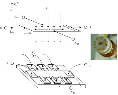
Figure 1: A typical quantized Hall resistance device
Typically, the samples used for metrological applications are in the form of a rectangular shaped Hall bar semiconductor heterostructure device as shown in Figure 1. When a sample is placed at a sufficiently low temperature (for example, below 1 K), perpendicular to a strong magnetic field (for example, magnetic flux density up to 14 T), such as a low temperature cryostat with a superconducting magnetic, the quantized Hall resistance RH can be obtained by measuring the ratio of the current ISD flowing through the source and drain electrodes of the sample to the Hall voltage VH. The Hall voltage VH is observed between potential electrodes attached to the edges of the quasi-two-dimensional layer of the sample.

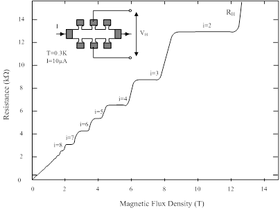
An experimental observation of the quantized Hall resistance of a typical device is shown in Figure 2. The quantum Hall effect appears as plateau in the Hall resistance of the sample and the quantized Hall resistance remains constant as the magnetic field is varied over the whole width of the plateau.
Under such experimental condition, the quantized Hall resistance (RH) produced at the device is given by

where h is the Plank’s constant, e is the elementary charge, and i is a positive integer, I = 1, 2, 3, 4, … that denotes a particular plateau of the quantized Hall resistance. The quantized Hall resistance is precisely reproducible at the device and is irrespective of the geometric details of the experiments or the imperfection of its materials.

Figure 2:Quantised Hall resistance measurement
The mises en pratique of the SI ohm
There is a difference between the definition of a SI unit and its realisation. The definition of each SI base unit is carefully drawn up so that it is uniquely sound in theoretical basis upon which the most accurate and reproducible measurements can be made. The practical realization, or the “mise en pratique” of the definition of a unit is the procedure by which the definition may be used to establish the value and associated uncertainty.
The ohm (Ω), the SI unit of electric resistance, is a derived units uniquely defined by the relation 1 Ω = 1 m2 kg s–3 A–2. However any method consistent with the laws of physics could be used to realize any SI unit. The ohm is also expressed as “the electric resistance between two points of a conductor when a constant potential difference of 1 volt, applied to these points, produces in the conductor a current of 1 ampere, the conductor not being the seat of any electromotive force”.
Von Klitzing constant
The discovery of the quantum Hall effect by Klaus von Klitzing in 1980 has provided a means to establish an intrinsic standard that relates the ohm, the electrical unit of dc resistance, to the invariant fine-structure constant. Based on the recommendation of the Consultative Committee on Electricity and Magnetism (CCEM), the International Committee of Weights and Measures (CIPM) at its 1988 meeting adopted the von Klitzing constant RK. The RK-90 with an uncertainty of 2 parts in 107 came into effect on 1 January 1990 as an exact adoption of the von Klitzing constant RK. National metrology institutes adjusted the value of their representation of the ohm to be consistent with this new internationally agreed value. Based on a review of the relevant RK data as existed at the time, the CCEM decided in September 2000 that the assigned relative standard uncertainty of a perfectly realized ohm representation based on the quantum Hall effect and RK-90 should be 1 part in 107. This decision was subsequently approved by the CIPM in October 2000.
The von Klitzing constant RK, now accepted as a universal quantity, is assumed to be exactly equal to the invariant quotient of fundamental constants h/e2, where h is the Plank’s constant, e is the elementary charge, and the quantised Hall resistance expressed in terms of the conventional value of RK-90 is

where i is an integer which defines a particular plateau of the quantized Hall resistance.
In contrast to all classical resistance artifacts, the quantized Hall resistance does not alter with time, and it does not suffer from mechanical shock during transportation. It can reproduce the SI unit of ohm with precisely the same values in every country, and thanks to Prof von Klitzing, metrologists around the world now have a universal reference for the unit of resistance.
Realisation of Primary Resistance Standard at NMC
The quantized Hall resistance has been widely used to establish a highly reproducible resistance primary standard with measurement uncertainty at a few parts in 109 level for traceability of dc resistance measurements.
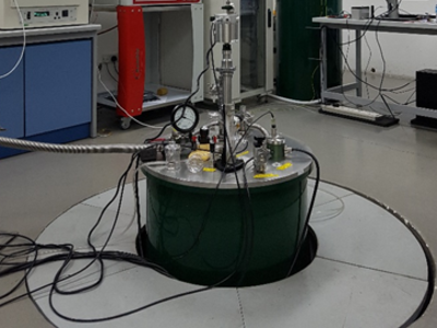
A new quantized Hall resistance primary system has been set up recently at NMC to replace aging system to continue the local indirect realisation of the SI unit of ohm at an absolute 12.906 4035 kΩ resistance reference, and maintained the resistance reference value by an ensemble of 100 Ω resistance standards. For transferring the realised resistance value at the best achievable accuracy, a new cryogenic current comparator resistance bridge is used to compare the ensemble of 100 Ω resistance standards against the quantized Hall resistance standard.
With the new system and capability established, NMC is able to compare 100 Ω resistance standards against the quantized Hall resistance at typical expanded measurement uncertainties (k = 2) better than 0.02 μΩ/Ω.
Resistance bridges such as the direct current comparator resistance bridge, potentiometric resistance bridge, dual-source resistance bridge and teraohm meter are then used to scale and transfer the unit of resistance from the ensemble of 100 Ω resistance standards to standard resistors from 0.1 mΩ to 100 TΩ. The scaling of resistance standards is periodically verified by cross-comparison of stable 1 Ω and 10 kΩ standard resistors as check standards to ensure the quality of resistance measurements.
With the advancement in science and technology, there is a growing need for resistance measurements with lower uncertainty and better uniformity among the national metrology institutes. High precision measuring instruments such as resistance and thermometer bridges require measurement uncertainties at a fraction of 0.1 µΩ/Ω, which can only be achieved by a quantized-Hall resistance standard.

Figure 3: NMC’s quantized Hall resistance primary standard and cryogenic current comparator resistance bridge
A*STAR celebrates International Women's Day

From groundbreaking discoveries to cutting-edge research, our researchers are empowering the next generation of female science, technology, engineering and mathematics (STEM) leaders.
Get inspired by our #WomeninSTEM
