Fluid Dynamics
To develop cutting edge modelling, simulation and data intelligent solutions for fluid flow, thermal/mass transfer and fluid related multi-physics applications. IHPC focuses on insight of fluid phonomena, new numerical algorithms, and advanced simulation approaches. To support urban sustainability and industry innovation through model simulation and design optimisation.
FLOW SYSTEM INTEGRATION
The Flow System Integration Research Group aims to develop methodologies to bridge the Cyber World to the Physical World by developing and integrating machine learning and physical fluid models into a virtual/physical platform for design, testing, optimisation, and operation. Our primary research areas include:
- AI for process model and control (APMC)
- Sensing and data fusion techniques for digital twin and optimal control (SDFT)
- Digital twin technologies for decision making (DT)
- Flow control and process optimisation (FCPO)
The framework is built on combinations of physics-based models, reduced-order models, machine learning models, and data assimilation models. Depending on specific applications, a suitable combination of the models will be chosen based on the models’ strength, validity and applicability. We also aim to further develop this framework for inverse modelling of specific engineering designs and discover hidden parameters in physical systems, such as the source leak location in a dispersion problem.
The example below demonstrates a high-Re flow simulation. Compared to the full model result (Fig. A), a combined Physics-Based Reduced-Order Model (PBROM) and Neural Networks (NN) method achieve very good results (Fig. B) in a few seconds, while the full model (Fig. A) simulation takes a few hours.
-and-neural-networks-(nn).png?sfvrsn=5758a54f_0)
High-Re flow simulation
The example below shows the outcome of the sensor down-selection process for the model predictive control system to automate the shot peening machine. In particular, the pressure sensor locations are chosen at the inlet and on the nozzle based on the CFD simulation results (Fig A). The measurement results (Fig B) indicate that the pressure sensors and their location can accurately measure the kinetic energy transferred from the airflow to peen velocity at the impact, and kinetic energy from the peens to the treated component surface. As the result, the pressure measurement data can represent the level of intensity for real-time tracking to support optimal control.
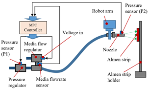
Fig A. Pressure sensor’s placement for automated shot peening machine
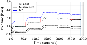
Fig B. Real-time pressure measurement signal
In FCPO, IHPC develops a cutting-edge model predictive control (MPC) platform with powerful optimisation engines for advanced manufacturing processes. MPC utilises a dynamic model within a robust optimisation algorithm for a process to optimise the control variables at every point in time while anticipating future events. In our development, state-of-art model order reduction (MOR) methods, such as PBROM, are integrated into MPC to enable accurate and real-time controls of linear/nonlinear processes. In addition, the concepts of online machine learning for control are also implemented to update the control policies in real-time to enable the power of adaptive control for highly nonlinear dynamic process systems. As such, in applications, MPC helps to improve efficiency, productivity and product quality, whilst reducing operational cost and time.
The example below shows a schematic diagram of the experimental system (the shaded box is our MOR-MPC control implementation) for a chemical reaction process. The MOR-MPC (Fig 3) approach is applied to control the transformation of synthesis of 3-piperidinopionic acid ethyl ester by a Michael addition scheme from piperidine and ethyl acrylate with water effect. The MOR-MPC approach achieves about 500 times faster than the original process model, while the relative error is below 0.1%.
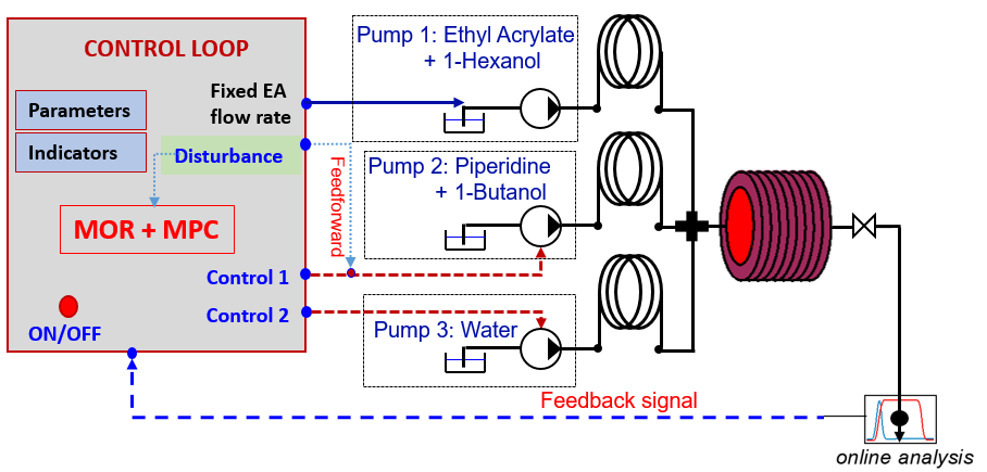
Fig 3. MOR-MPC control implementation
Multi-Physics Modelling
The Multi-Physics Modelling Research Group focuses on capabilities which integrate complex physics with CFD models by developing advanced numerical algorithms to tackle the challenging, industrially-relevant, multi-physics problems which cannot be addressed by traditional CFD alone. Our research interests include, but are not limited to:
- Rheology Physics
Developing capabilities for robust CFD models to couple new physics for colloidal dynamics to account for macroscale effects for the translation from small-scale to large-scale applications. Our research covers from the bubble/droplet dynamics to solid particle movement which are applied in oil and gas industry, advanced manufacturing process, water treatment, food and beverage to consumer care products.
- Interactive Physics
Exploiting flow interaction, especially turbulent flow, with complex materials, flexible structures, and external fields towards better design, production, and operation. Our research spans from direct numerical simulation (DNS) of turbulent and transitional flows to tackle fundamental problems in the aerospace sector, to the development of robust Reynolds-averaged Navier-Stokes models for immediate application in the MedTech and Precision Manufacturing sectors. - Transport Physics
Developing capabilities for high fidelity CFD models to predict multi-physics flow and transport and to understand any consequent complex phenomenon. Our research includes a variety of applications such as nuclear fusion, energy efficiency in green data centers, additive manufacturing processes, water desalination and high-performance thermal management systems for electronics.
• Viscoelastic Fluid Simulations in Abrasive Flow Machining Processes
Abrasive flow machining (AFM) is a finishing process that has been traditionally applied to deburr and polish internal workpiece geometries with difficult-to-reach areas. AFM media can vary in abrasive particle size, the concentration of abrasive particles, blending oil type and amount, type of viscoelastic polymer and lifetime of the media. In other words, AFM media is a non-Newtonian fluid with complex viscoelastic rheological characteristics. With the development of the viscoelastic fluid solver in OpenFOAM, we have the capabilities to simulate the behaviour of abrasive media in AFM processes to estimate material removal distributions on additive manufacturing components. In addition, a built-in graphical user interface (GUI) was developed with the simulation platform (AFMSIM) for targeted AM engineers with basic CFD knowledge to use. Furthermore, the log-conformation tensor representation (LCR) approach was implemented to stabilize the solver under high Weissenberg numbers (We=λṙ, λ: relaxation time, ṙ : shear rate). Fig 1 demonstrates material removal distribution, flow field, and two-phase profiles of AM components under AFM processes.1/2.
1. Wu, C.H., Kum, C.W., Wan, S. Y. M., Abu Bakar, A. M., Numerical and experimental investigation of abrasive flow machining of branching channels. International Journal of Advanced Manufacturing Technology. 108, 2945–2966 (2020).
2. Kum, C.W., Wu C.H., Wan, S. Y. M., Kang, C.W., Prediction and compensation of material removal for abrasive flow machining of additively manufactured metal components. Journal of Materials Processing Tech. 282, 116704, (2020).

Fig.1 (a) Material removal distribution of an impeller; (b) Material removal distribution (upper) and flow field around guiding vanes (lower)2;(c) Normalised polish strength of a complex internal AM channel; (d) Two-phase profile of abrasive media with velocity contour in a branching channel
We propose a self-consistent multiscale model to bridge the gap between hydrodynamic transport and deposition, accounting for convective-diffusive transport and Derjaguin-Landau-Verwey-Overbeek (DLVO) forces. The colloidal deposition gradient can be spatially controlled through delicate balance of fiber zeta potential, ionic strength and hydrodynamics (Fig. 2). Our model extends freely to oriented two-fiber and multi-fiber arrays (Fig. 3).

Fig. 2: (a) Colloidal concentrations and flux lines in a single fiber flow cell. Deposition efficiency depends on (b) Péclet number and (c) ionic strength.
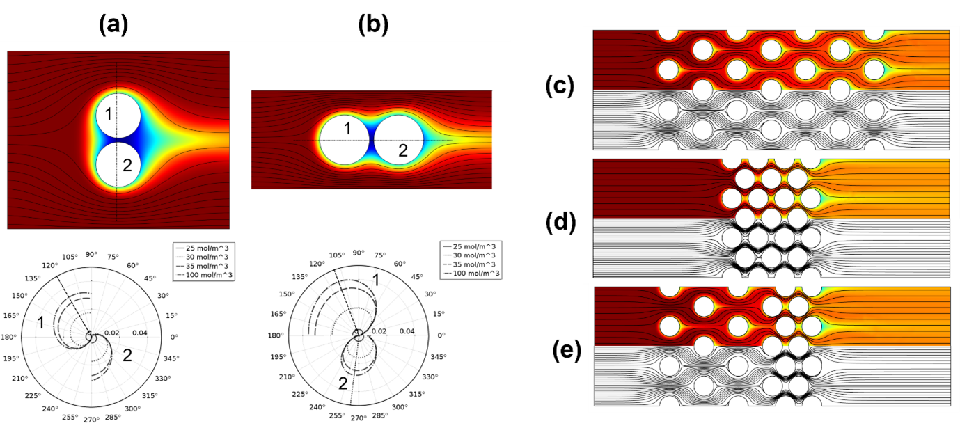
Fig. 3: Colloidal concentrations with local flux distributions for (a) vertical and (b) horizontal two-fiber arrays, scalable to (c) porous, (d) compact and (e) composite multi-fiber arrays.
• Aerospace
Our recent work involving DNS, illustrated in Fig. 4, includes evaluating how minor imperfections on an air foil can influence the transition location, and therefore the performance of the air foil. Results such as this help the airframe manufacturers to determine appropriate fabrication tolerances.
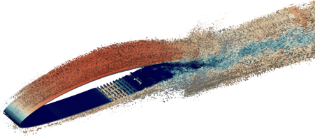
Fig. 4: Direct numerical simulation of the transitional flow over a natural laminar flow air foil.
We develop Reynolds averaged Navier-Stokes (RANS) equations-based robust turbulence models for wide range of applications ranging from medical to aerospace to advanced manufacturing sciences. The coating formation on a substrate during the cold spray additive manufacturing process is shown in Fig. 5. With the help of our improved RANS model we could enhance the simulation accuracy and capture the coating characteristics seen in experiments 3/4.
3. Sundaravadivelu, K., Turbulence Transition Prediction in Wall Bounded Flows using Improved Two Equation Reynolds Averaged Navier Stokes (RANS) Models, IHPC-TD-FD-2020-031.
4. Sundaravadivelu, K., Absi, R., Turbulent kinetic energy estimate in the near wall region of smooth turbulent channel flows, Meccanica, 56, 2533–2545 (2021).

Fig. 5: Cold spray particle impact footprint.
• Magnetrons Sputtering Configuration
Fig 6 shows Magnetrons Sputtering configuration. Under the strong electric field, the Argon gas is ionized. The electrons ejected from the cathode are accelerated through the cathode fall region into the bulk of the plasma. They may acquire enough energy to ionize the background gas, creating a new electron-ion pair. The magnetic field traps the electrons so they are confined by the magnetic field lines, rather than escape to the walls. The trapping of the electrons results in more ionization collisions with the background gas and higher plasma densities than would normally be expected at such low pressures.
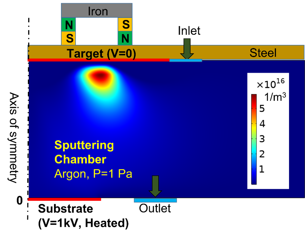
Fig. 6: Magnetrons Sputtering configuration
We have developed an advanced CFD model to simulate air flow and heat transfer in a data centre. The model is then applied to assess the performances of different test parameters of cool air management systems in data centres, as illustrated in Fig. 7. The simulation results compare reasonably well with experimental data measured by KoolLogix a local SME. The validated digital model can be applied for multiple heat removal units in a large-scale data centre simulation.
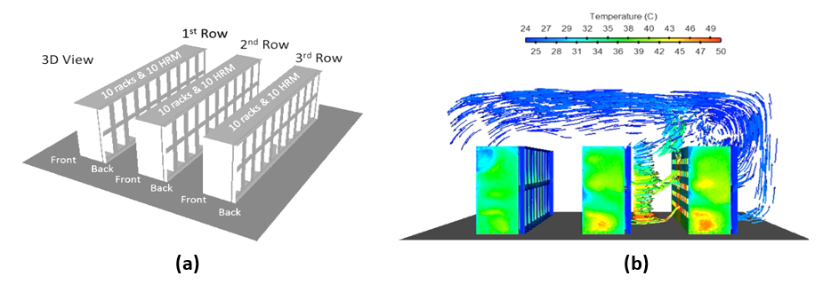
Fig. 7: (a) Computational domain and (b) simulation results for a cooling redundancy scenario study.
We have developed CFD model to investigate boiling in micro-channel with pin-fin structures. Figure 8 shows the vapor bubble formations in the cooling of electronic chips. The channel is fully filled with liquid and the temperature at the bottom wall has high temperature. When the liquid increases to its boiling temperature, vapour bubbles start to occur at the bottom. Driven by the buoyancy force, the generated bubbles rise gradually due to the much smaller density compared with the liquid. With the CFD model developed, we can predict the chip temperature distribution as well as critical heat flux in the thermal management system.
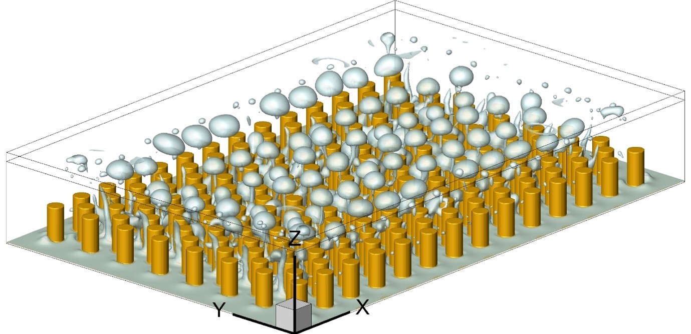
Fig. 8: Vapor bubble generation during the phase change process.
Multi-Scale Modelling
The Multi-Scale Modelling Research Group focuses on developing methods and algorithms for scalability modelling across multi-dimensional space, time scales, and process methodologies. The goal is to expand modelling and simulation capabilities through the consolidation and approximation of data across different domains.
Our research focuses on three main areas:
- Dimensional Adaptivity: Model features & adaptively rescaling to perform high-fidelity simulations in reduced/parameterised spatial dimensions
- Temporal Scaling: Capabilities to traverse and integrate different time scales to understand phenomena of interest
- Process Coupling: Amalgamate different types of models with CFD simulations to obtain more accurate depictions of system functionality
3D CFD Simulations for Cryogenic Bunkering Leakage and Explosion
Shipping emission is a major source of pollutants and greenhouse gases. As countries become increasingly environmentally conscious, the shipping industry is expected to adopt measures to reduce or cap emissions. It is expected that in coming years, regulatory bodies governing the shipping industry will adopt increasingly stringent targets on emissions.
To reduce shipping emissions, Singapore’s maritime industry is moving to green/carbon neutral marine fuels. Green/carbon neutral fuels include fuels like LNG, LPG, ammonia, hydrogen, methanol and biofuels. As these fuels are expected to become more common, use of and demand for specialized facilities catering to these fuels is expected to increase.
One such facility is the bunkering station (shown in Fig. 1).
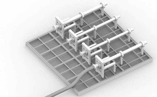
Fig 1: Example of bunkering facility.
IHPC supports the marine industry through development of computational tools and models for simulation and risk assessment. Within the Fluid Dynamics department, the primary simulation tools are Computational Fluid Dynamics (CFD) codes. IHPC develops, tests, applies and validates these codes against real-world problems in the marine industry. An example of a CFD study applied to the bunkering station is shown in Figs. 2 and 3. Here, the effects of an enclosure on leak dispersion is evaluated. Fig. 3 shows the plume dispersion in the presence of wind. Fig. 3 shows that, with the inclusion of an enclosure, the plume dispersion is limited.
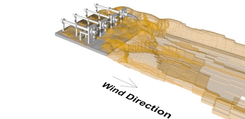
Fig 2: Plume spread in the presence of wind.
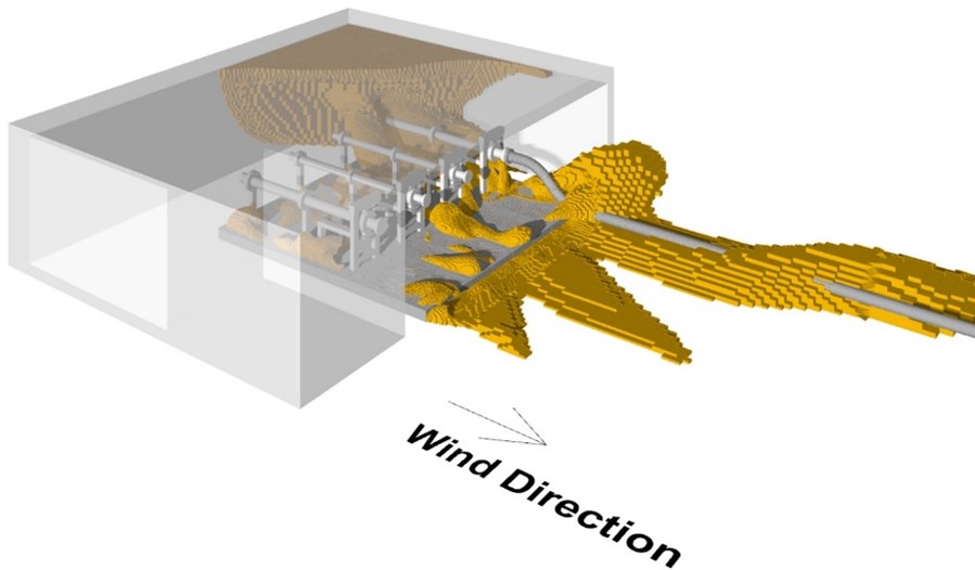
Fig 3: Plume spread in the presence of wind and an enclosure.
Nguyen V.-T. et al., “Reduced order models for uncertainty quantification of gas plume from leakages during LNG bunkering (2022)”, Journal of Loss Prevention in the Process Industries, Vol. 76, 104724
Computational Fluid Dynamics (CFD) with Reynolds-averaged Navier-Stokes modelling is commonly used for gas dispersion or flow in the urban canopy. A comparison with field measurements has shown that CFD can accurately reproduce most flow phenomena, such as flow separation, recirculation, and flow reattachment. However, CFD computations are time-intensive to run and require high-performance computing. This can be time-consuming for real-time toxic gas release or initial planning studies for new construction. Fast-response or mass-consistent models coupled with machine learning and sensor data offer a balance between speed and accuracy.
Some of the topics being addressed include:
1. Machine learning-driven smart meshing
2. Physics-informed machine learning models for built environment and gas dispersion
3. Hot-spot identification using a fast thermal solver
4. A mass-consistent fast solver for gas dispersion studies
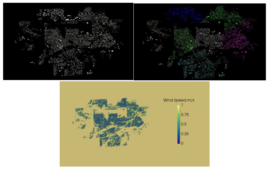
Fig 4: (Clockwise from Top) Original STL model
(Top Right) Model split according to machine learning. Users can specify the number of zones and buildings that must be grouped and (Bottom) Simulations performed using the split model. Cell count was reduced from 43 million for the original model to 17 million for the split model.
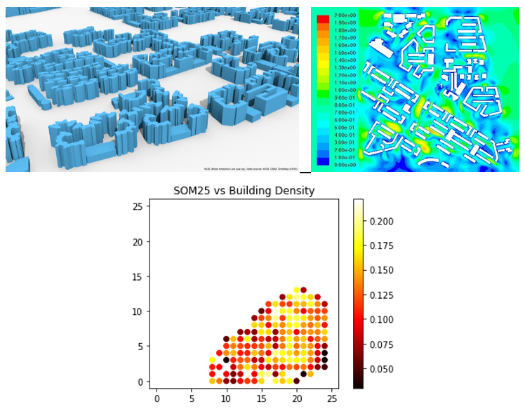
Fig 5: (Clockwise from top) Typical layout of a district in Singapore (Top Right) Output from CFD simulations used to train the machine learning model (Bottom) Mean absolute error in the prediction of pedestrian level wind speed using the machine learning model.
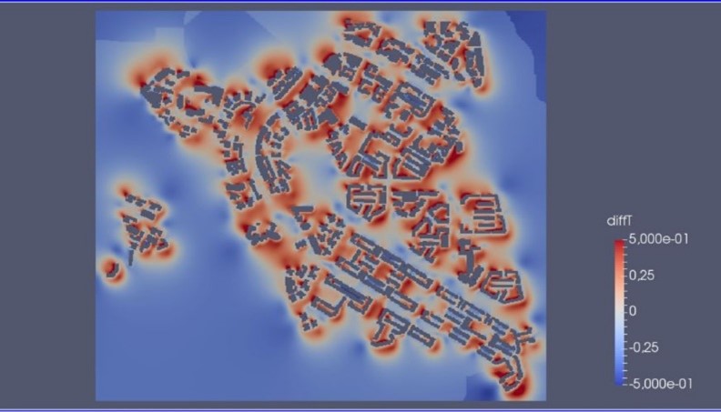
Fig 6: The image represents the difference in the predicted temperature using a complete CFD solver and a fast solver for hot spot identification. The fast solver requires 10% of the complete solver's computational time, and the temperature differences show a consistent systemic bias and can be corrected using machine learning.
Mesoscale and microscale numerical modelling for urban climate
There is a growing demand for switching to renewable energy sources worldwide from conventional coal and oil-based power producing systems. Wind farms are becoming widely popular and growing significantly worldwide among the different renewable energy sources. However, this poses a different set of challenges.
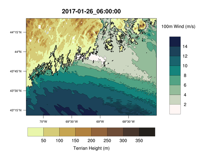
Fig 7: Real-time wind speeds near Gulf of Maine from COAWST simulations
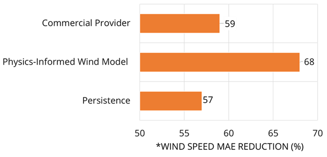
Fig 8: Mean absolute error reduction from our in-house physics informed wind model in comparison to existing commercial solution and persistence model for an operating wind farm.
Some of the on-going research projects are:
1. Physics-informed wind model for real-time forecasting
2. Developed of coupled framework for offshore wind farm siting and forecasting
3. Physics informed machine learning models for wake predictions in a wind farm
Process Coupling
Urban Physics Modelling
Urban Physics is an emerging discipline, incorporating relevant branches of physics, environmental chemistry, aero-dynamics, meteorology, and statistics. Modelling urban microclimate has a direct effect on improving the comfort and health of city dwellers, including reducing the energy demand of the city.
General research activities to include
- Climate (& Meteorology) across the Scales
- Urban Climate (Phenomena & Interactions) & Urban Energy
- Turbulence, Uncertainty Quantification and Data Science
- Fast-response Modelling
- Methods: Computational Fluid Dynamics (CFD) & Laboratory Modelling (Wind tunnel)
- Human thermo-physiology and heat stress, Urban pollutant dispersion
- Chin Chun Ooi, Pao-Hsiung Chiu, Venugopalan Raghavan, Stephen Wan & Hee Joo Poh, Porous Media Representation of Louvers in Building Simulations for Natural Ventilation, Journal of Building Performance Simulation, Vol. 12 (2019), Issue 4, 494 – 503, DOI: 10.1080/19401493.2018.1510544
- Bharathi Boppana, Chin Chun Ooi, Daniel Wise, Edward Zhmayev, Hee Joo Poh, CFD Assessment on Particulate Matter Filters in Urban Areas, Sustainable Cities and Society, 46 (2019), 101376, doi.org/10.1016/j.scs.2018.12.004
Our tree modelling focuses on the pipeline to convert acquired data in the form of LiDAR point clouds where individual tree properties such as height, trunk width can be used to build a tree parameter database related to the common tree species found in Singapore. The first step in this process is to separate the points related to the leaves and branches, and thereafter reconstruct a model of the tree branching structure. This allows us to extract the necessary parameters.
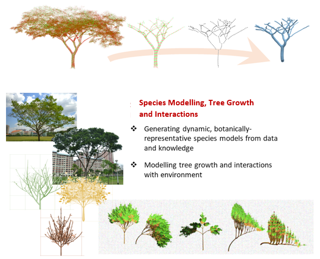
Fig 9: Tree modelling pipeline to reconstruct tree branching structure and build a parameter database of the common tree species in Singapore.
Impacts and Applications for Stakeholders
- Digital twin cities, e.g., Virtual Singapore
- Environmental simulations, e.g., tree health, tree fall risk, wind-tunnel, tree shading/cooling, pollutions
- Greenery & urban management & planning, e.g., tree health assessment, tree pruning, tree interactions, sky gardens
- L. Gobeawan, E. S. Lin, A. Tandon, A. T. K. Yee, V. H. S. Khoo, S. N. Teo, Y. Su, C. W. Lim, S. T. Wong, D. J. Wise, P. Cheng, S. C. Liew, X. Huang, Q. H. Li, L. S. Teo, G. S. Fekete, and M. T. Poto, “Modeling trees for Virtual Singapore: From data acquisition to CityGML models,” International Archives of the Photogrammetry, Remote Sensing and Spatial Information Sciences, vol. XLII-4/W10, pp. 55–62, 2018
- P. H. Joo, C. W. Leong, D. J. Wise, L. C. Wan, B. C. Khoo, L. Gobeawan, Z. Ge, E. Yong, P. J. Xin, V. S. G. Raghavan, S. S. Jadhav, L. Jing, C. Y. D., L. H. Pueh, D. C. Burcham, D. Lee, K. W. Li, and I. Lee, “Wind load prediction on single tree with integrated approach of L-system fractal model, wind tunnel, and tree aerodynamic simulation,” AIP Advances, vol. 10, Jul 2020
- L. Gobeawan, S. E. Lin, X. Liu, S. T. Wong, C. W. Lim, Y.-F. L. Gaw, N. H. Wong, P. Y. Tan, C. L. Tan, and Y. He, “IFC-centric vegetation modelling for BIM,” ISPRS Annals of the Photogrammetry, Remote Sensing and Spatial Information Sciences, vol. VIII-4/W2-2021, pp. 91–98, 2021
Resource-Efficient Accurate Prediction in Fluid Domain (RAPID)
The Resource-Efficient Accurate Prediction in Fluid Domain (RAPID) Research Group focuses on capabilities that boost the efficiency of numerical analyses, evaluations, and predictions by developing advanced algorithms, methodologies, and technologies.
Our research focuses on four main areas:
- Machine Learning (ML): Develop ML algorithms to extract information from data, translate it into knowledge about the underlying fluid physics and automate tasks related to flow control and design optimisation. Data-driven methods such as Reduced Order Methods (ROM), Surrogate-based methods, and Neural Network methods and their variations are included in this area.
- Empirical & Theoretical models: Extend empirical models and theory-based models for highly efficient analyses, evaluations, and predictions. Examples of this category include coupling CFD and potential flow in the far field and near field, simulation using potential flow theory-based methods, propeller performance prediction with disc method, and strip theory-based flow analysis.
- Quantum Computing: Develop quantum algorithms, and get ready for practical engineering applications in optimisation, data analysis, and fluid dynamics simulations.
- Graphic Processing Unit: Take advantage of its high efficiency for algorithms to process large blocks of data in parallel for simulation, deep learning, and autonomous operations.
PDEs such as the Navier-Stokes Equations are fundamental to important problems in many domains including complex flow phenomena. We are working on methods to adapt and use Neural Networks (NNs) for forward, inverse, and surrogate modelling of flow problems. These include developments in physics-informed neural networks and data-driven neural network methodologies for various problems in fluid dynamics, including forward problems (Fig 1), inverse problems (Fig 2), and surrogate modelling (Fig 3).
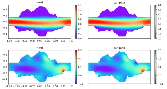
Fig 1: The u- and v-velocity contour from the solutions obtained by CFD simulation (1st column) and can-PINN (2nd column) for the 2D complex channel problem at Re=400. The median solution from 25 independent runs is shown.
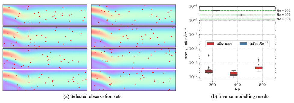
Fig 2: (a) Eight random observation sets in the inverse backward facing step problem, where the can-PINN is applied to simultaneously infer the unknown Re coefficient in the incompressible N-S equations and to solve the solution based on limited observations (n=30, in red). (b) The distribution of u&v MSE and inferred RE-1 obtained from the can-PINN for Re = 200,400 & 800. The green dashed lines and shaded areas indicate the ground truth RE-1 and their 10% error bounds. Results are based on 20 independent runs.

Fig 3: Sample contour plots of flow fields from CFD and U-Net-MG for the oscillating NACA 0012 foil under (a) energy harvesting mode, and (b) propulsion mode illustrating good performance by the trained surrogate models.
Data assimilation (DA) refers to methodologies for combining mathematical models simulating complex systems and measurements or observational data in order to improve estimates of the system state. The technique is demonstrated for wind load evaluations on the LNG carrier GALEA (Fig 4). With 24 pressure sensor data from wind tunnel tests, the pressure distributions on the whole vessel surface are reconstructed successfully through ROM, and the force coefficients obtained from the gappy POD based DA show a good agreement with the wind-tunnel measured results and those obtained from ROM simulations (Fig 5).
X.Q. Xing, M.H. Dao, B. Zhang, J. Lou, W.S. Tan, Y. Cui, B.C. Khoo, 2022, “Fusing sensor data with CFD results using gappy POD”, Ocean Engineering, 246, 110549.
.png?sfvrsn=c32a9056_0)
Fig 4: Framework of ROM and DA
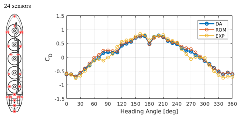
Fig 5: Comparison of the wind loads on GALEA from experiment, ROM, and gappy POD-based DA prediction
The classical-quantum hybrid variational quantum algorithm has emerged as a promising strategy for near-term noisy quantum devices. Using a parameterised hardware-efficient Ansatz, quantum circuits can be constructed to solve partial differential equations with high fidelity. Our algorithm extends economically to higher-order time-stepping schemes and can be adapted to solve other evolution equations, such as reaction-diffusion and incompressible Navier-Stokes equations.
Please refer to ITA - Quantum Computing for more quantum computing related studies in IHPC.
Numerical models for the study of motion response of the marine-offshore structures are notorious for the high demand for simulation time. In this in-house effort, we adopt the concept of domain decomposition (DD) method to reduce the simulation time by coupling the potential and viscous flow models.
X. Lu, M.H. Dao, and Q.T. Le, “A GPU-Accelerated Domain Decomposition Method for Numerical Analysis of Nonlinear Waves-Current-Structure Interactions”, Ocean Engineering, 2022
The near field contains the structure and a relatively small region of the domain where the viscous model is solved for accurate solutions. The simplified potential model is then solved in the far field for its fast speed and superior performance in simulating wave propagation in the large domain. A layer of an overlapping zone is for information interchange between the potential solver and the CFD solver, as shown in Fig 6 (a). A good example is the simulation of seakeeping response for vessels under rogue waves. The coupled DD solver is also implemented to utilise the graphic processor unit (GPU) accelerations. The method is well validated and one of the validation cases is illustrated in Fig 6 (b).
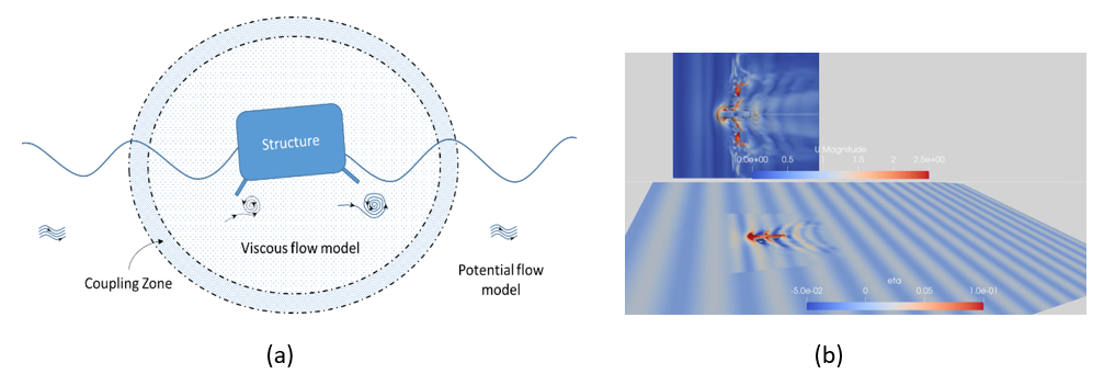
Fig 6. Potential and viscous models in the simulation of wave-structure interaction problems:
(a) The schematic of the coupling and (b) Self-propulsion of ship hull in regular waves.
A*STAR celebrates International Women's Day

From groundbreaking discoveries to cutting-edge research, our researchers are empowering the next generation of female science, technology, engineering and mathematics (STEM) leaders.
Get inspired by our #WomeninSTEM
.png?sfvrsn=ff199933_15)